In 1980, Intel introduced the 8087, a chip that made floating-point operations much faster in the IBM PC and other systems. Although the 8087 supports advanced operations such as tangents, square roots, and logarithms, this article focuses on basic arithmetic operations: addition and subtraction. The 8087 provided a spectacular speed improvement over the 8086 processor, speeding up addition by a factor of almost 100, and complicated operations by even more.1 In this article, I examine the 8087's microcode and circuitry to explain exactly how floating-point addition and subtraction are implemented, including numerous special cases for infinities and other special values.
To explore the 8087's circuitry, I popped the lid off a chip with a chisel and used a microscope to create the high-resolution image below. The microcode ROM is the large rectangular region in the center of the die, holding the 1648 micro-instructions that control the chip. The bottom half of the chip (red box) is the datapath, the circuitry that performs floating-point calculations on 80-bit values.2
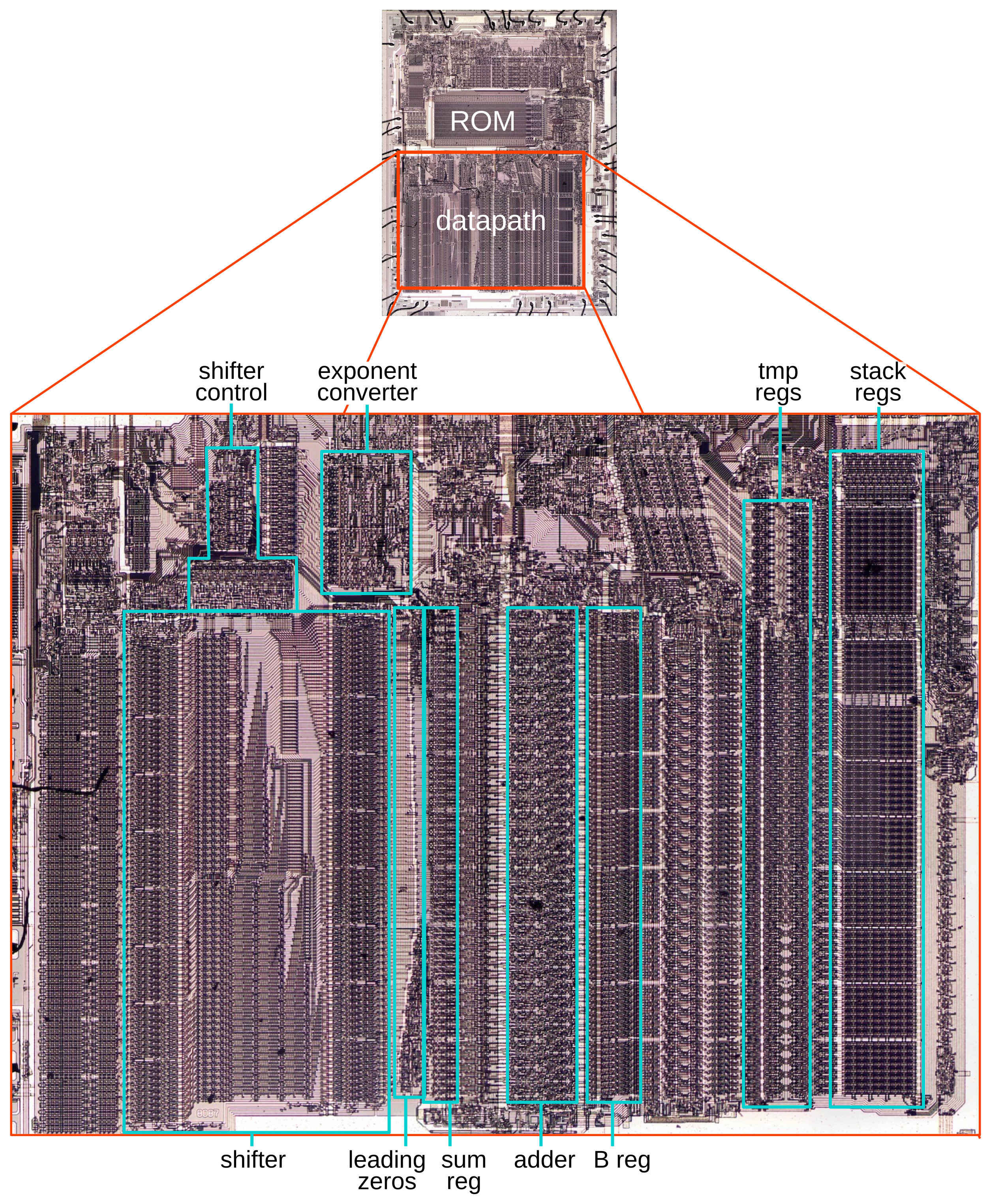
Zooming in on the datapath shows the functional blocks that are important for addition and subtraction. The key component is the integer adder, located in the center. It receives one argument from the B register and another argument from a component such as the temporary registers or the stack registers. The adder's output is stored in the sum register. The shifter can shift the bits in a value to the left or the right. The shifter occupies a lot of space on the die because its circuitry allows a value to be rapidly shifted by an arbitrary number of bits. Floating-point operations make heavy use of the shifter to align values; the leading zero circuitry counts the number of zero bits or bytes on the left of a value so they can be shifted away. The exponent converter processes exponents, detecting overflows and underflows. These specialized circuits helped the 8087 achieve its high performance.
Floating-point addition and subtraction
Most computers use integers as their basic representation for numbers. But many applications need to use numbers with a fractional part, such as 1.23. Moreover, integers have a very limited range: a 32-bit integer can express numbers from about -2 billion to 2 billion. To solve these problems,3 computers usually implement floating-point numbers, which provide fractional numbers over an enormous range.
In most cases, a floating-point number is represented by sign × significand × 2exponent.
The significand is a binary number of the form 1.bbb…:
a leading 1, followed by the binary point (the binary equivalent of the decimal point) and the rest of the bits.4
In a binary number, each bit represents a power of 2. For the fractional part, the part
after the binary point, the powers of 2 are negative: 2-1, 2-2,
and so forth.
So the binary number 1.1 is 1 + 1/2, or 1.5 in decimal. Similarly, binary 1.0011 is
1 + 1/8 + 1/16 or 1.1875.
The exponent allows numbers to escape the limited range of the significand.
For instance, 1.1 (binary) × 28 is 304.
With larger exponents, floating-point numbers can cover a huge range;
even a 32-bit short floating-point number covers a range exceeding 10-36 to 1038.
Floating-point addition and subtraction are more complicated than integer operations. Before the numbers can be added (or subtracted), their binary points must be aligned, the same as aligning the decimal points for decimal numbers. After the operation, the exponent of the result must be adjusted, normalizing the significand so it starts with a 1 bit.
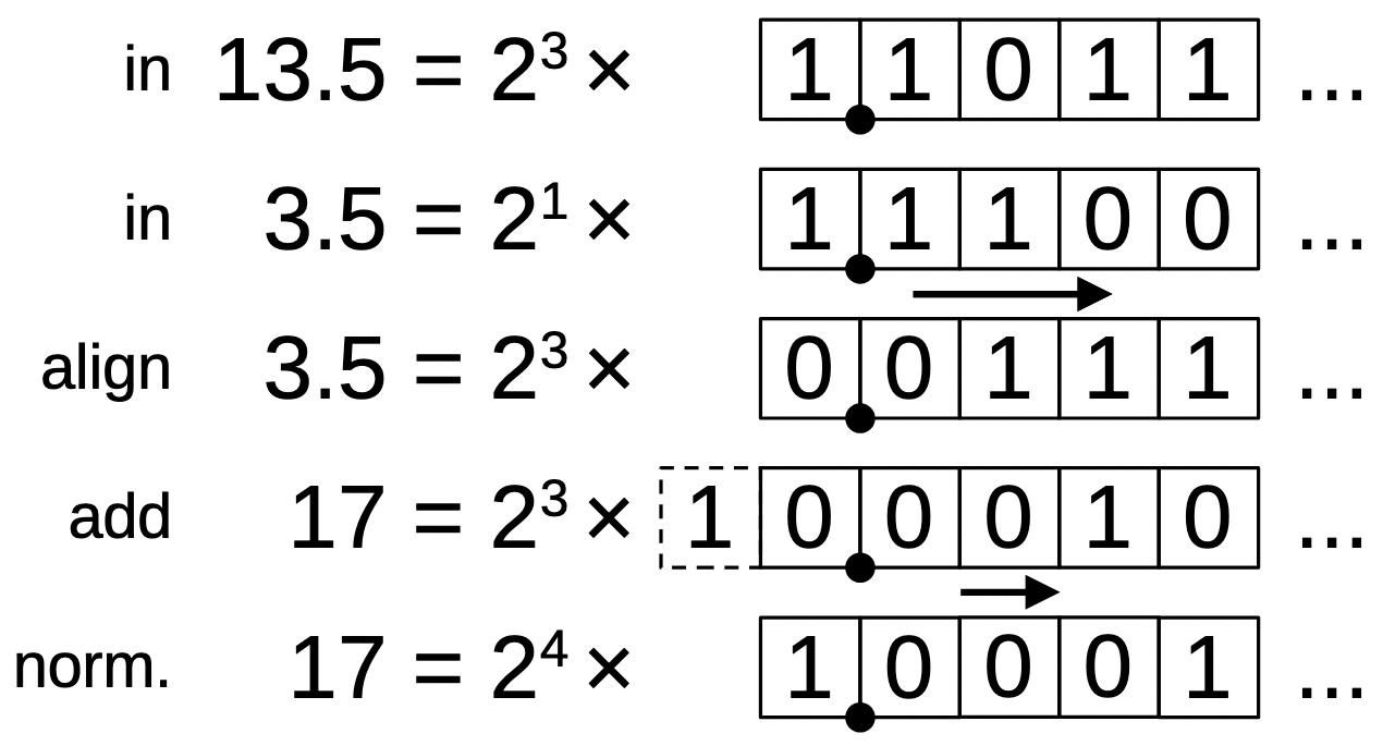
The diagram above illustrates a simple floating-point addition: 13.5+3.5.
The first two lines show the two arguments expressed with an exponent and significand.
Both arguments are normalized, so the leftmost bit is a 1.
Before adding, the second argument must be aligned—making the exponents equal—by shifting it two positions
to the right. (The difference between the exponents in this case is two.)
The values are then added, using integer addition on the aligned significands.
In this case, adding the values causes an overflow, an "extra" bit
on the left.
The result must be normalized by shifting it one position to the right and incrementing the
exponent by 1.
Floating-point subtraction is similar, but has a few more complications. The result can be positive, negative, or zero. The result can be orders of magnitude smaller than the arguments. The figure below shows a basic subtraction, 8-7.5. As with addition, the second argument is shifted right so the exponents match (i.e., the binary points line up). The two significands are subtracted with integer subtraction. The result is normalized by shifting to the left so the top bit is a 1. Unlike the addition case, normalization may require a large shift. In this case, the shift is four bits and the exponent is decremented by 4 to yield the result.
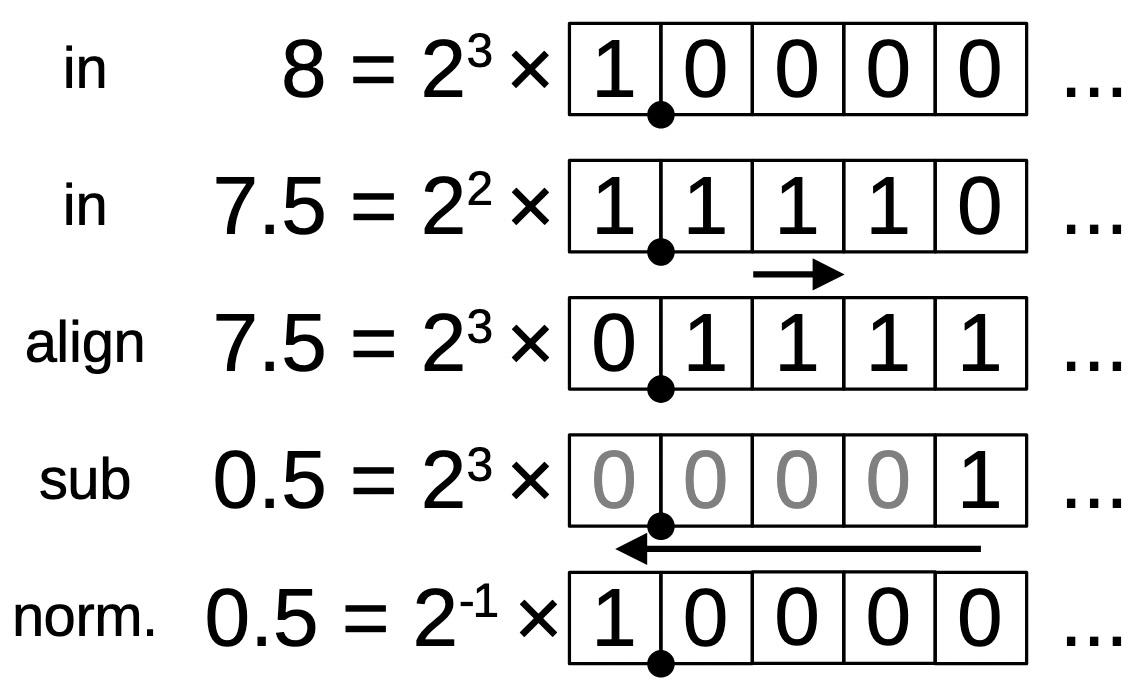
One complication with subtraction is that the result can be negative. If that occurs, the significand is made positive, and the sign of the result is flipped. Subtraction can also result in zero. In this case, normalization cannot be performed; instead, a special value +0 or -0 is returned as appropriate.
Relevant hardware details of the 8087
In this section, I'll explain some features of the 8087 that play important roles in the microcode implementation of addition and subtraction.
The 8087 supports a variety of data types, but
internally, the 8087 stores numbers in an 80-bit format called "temporary real".
A temporary real number has a sign bit, a 15-bit exponent, and a 64-bit significand.
The 15-bit exponent allows numbers that are absurdly large, over 104932.
The 64-bit significand supports extremely accurate numbers.
The exponent is stored with a "bias" of 16383 added to it. Thus, the stored exponent is always positive, even if the real
exponent is negative. For instance, an exponent of 1 is stored as 0x4000, and an exponent of -16 is stored as 0x3fef.
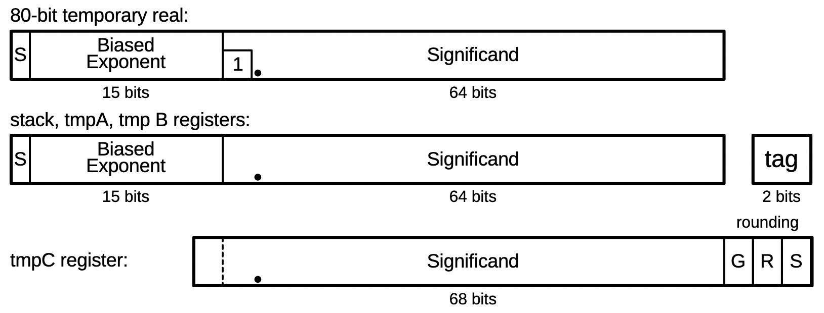
The 8087 has eight internal registers, organized as a stack. The programmer uses these registers when programming the 8087. Each register holds an 80-bit floating-point number. To optimize performance, each value in the register stack also has an associated "tag" value: zero, valid, special, or empty. A value of zero is tagged as zero. A "normal" floating-point value is tagged as valid. If the value is infinity, Not a Number (NaN), or a denormalized value, then it is tagged as special. Finally, an empty tag indicates that a register does not hold a value; this allows detection of stack underflow (reading an empty register) or stack overflow (storing to a non-empty register).
The 8087 also has temporary registers that it uses internally.
tmpA and tmpB are 80-bit registers, along
with two tag bits.
However, tmpC is different: it doesn't have a sign, exponent, or tag.
Moreover,
the significand is 68 bits; tmpC has an additional
bit to prevent overflow and three additional low-order bits for rounding, known as
guard, round, and sticky.
In the microcode, each 16-bit micro-instruction performs one low-level operation. Many of the operations move data from one register to another. Other operations provide conditional jumps, subroutine calls, and returns.
The heart of the 8087's processing is the 69-bit integer adder, which I discussed here.
(The adder has more than 64 bits because it has three rounding bits and a couple of
additional high-order bits for overflow and multiplication.)
Integer addition takes two micro-instructions. The first micro-instruction
specifies the first argument to add and selects various options such as
carry and rounding.
(For subtraction, an option complements the second argument.)
The second argument to the adder always comes from the B register, which confusingly is
unrelated to the tmpB register.
The result of the addition operation is placed in a special register called the sum register.
A second micro-instruction (which may be many instructions after the first) moves the result from the sum register to a destination.
Floating-point also makes extensive use of the bit shifter, which shifts a 68-bit value by an arbitrary number of positions, left or right; I wrote about it here. Like the adder, a bit shift operation takes two micro-instructions: the first moves a value to the shifter and configures the direction and amount of shift. The second micro-instruction moves the result from the shifter to a destination.
The addition/subtraction microcode
The 8087 implements almost all of its operations in microcode.
The basic math operations (addition, subtraction, multiplication,
and division) start by executing the same microcode (at decimal address #0001.
The microcode moves the two arguments into temporary registers tmpA and tmpB.
Normally, these arguments are taken from the stack registers. The arguments can also
be taken from memory, but I won't discuss that here.
Next, the microcode does a micro-subroutine call to handle the specific operation type. The 8087's microcode engine has a tiny ROM that holds a table of addresses, targets for microcode jumps or subroutine calls. Target 0 is special, however; it has three different addresses for multiplication, division, or addition/subtraction. (This is implemented by special-case circuitry in the ROM. When you're designing the chip, you can do weird, hacky optimizations like this if you want.)
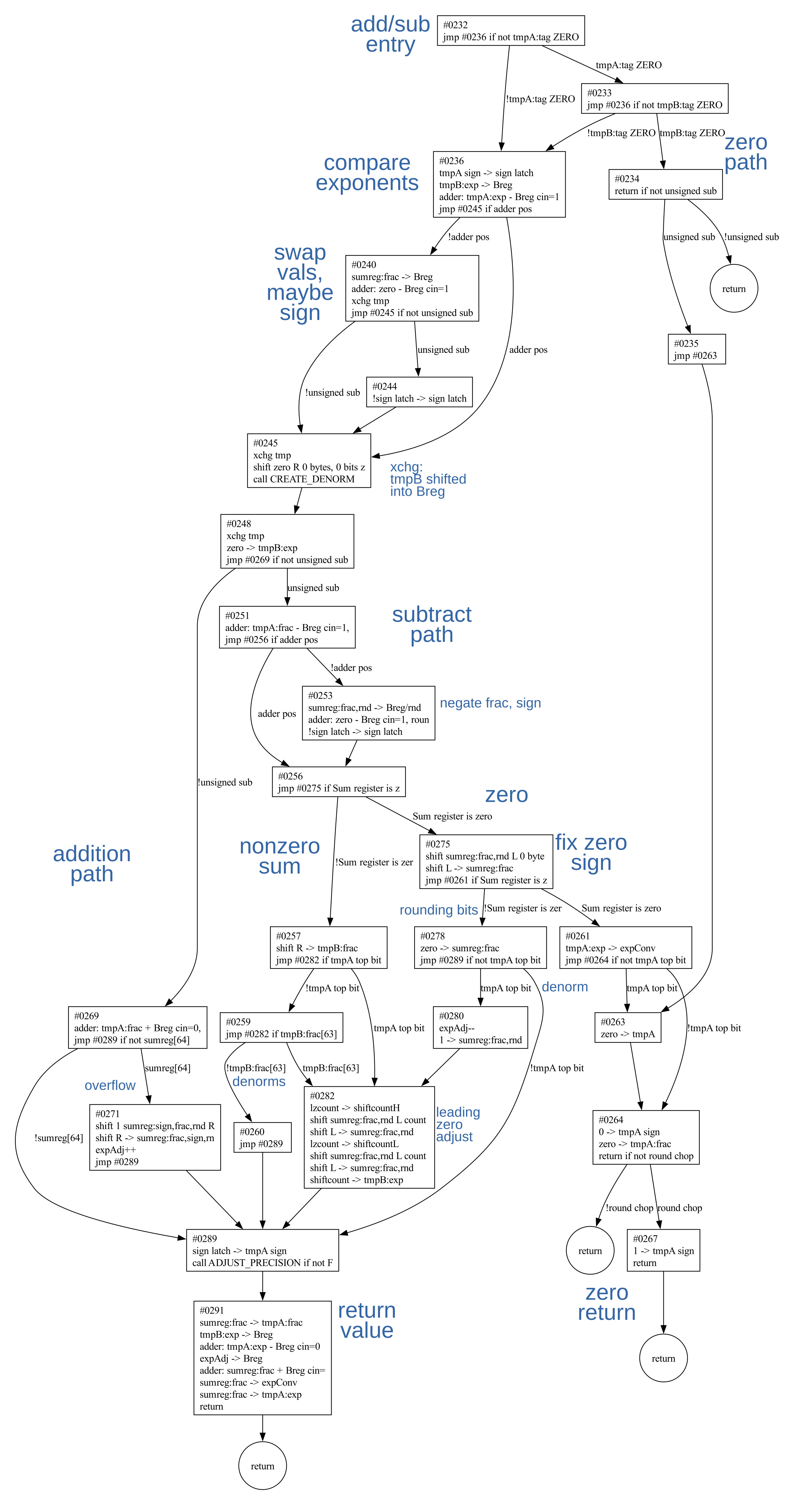
The addition/subtraction micro-subroutine starts at address #0232; this microcode
is shown below. The control flow is complicated, so I've put a flowchart in the footnotes.5
The microcode first handles the zero cases 0+0 or 0-0.
Next, it subtracts the exponents of the two arguments.
If the first argument has a smaller exponent (i.e., the result is negative), the arguments
are swapped so the argument with the larger argument is first.
(The 8087 keeps track of the sign of the result in the "sign latch"; if exchanging
the arguments would change the sign, the latch is toggled at #0244.)
#0232 jmp #0236 if not tmpA:tag ZERO Check for 0+0
#0233 jmp #0236 if not tmpB:tag ZERO
#0234 return if not unsigned sub 0+0 same signs
#0235 jmp #0263            handle 0+0 different signs
#0236 tmpA sign -> sign latch nonzero: tmpA sign to sign latch
#0237 tmpB:exp -> Breg
#0238 adder: tmpA:exp - Breg cin=1 compare exponents
#0239 jmp #0245 if adder pos
#0240 sumreg:frac -> Breg  swap if tmpB's exponent larger
#0241 adder: zero - Breg cin=1
#0242 xchg tmp
#0243 jmp #0245 if not unsigned sub
#0244 !sign latch -> sign latch toggle sign if swapping matters
#0245 xchg tmp             continue
#0246 shift zero R 0 bytes, 0 bits zero
#0247 call CREATE_DENORM   shift tmpB to match exponents
#0248 xchg tmp
#0249 zero -> tmpB:exp     store exp adjustment in tmpB:exp
#0250 jmp #0269 if not unsigned sub base addition?
#0251 adder: tmpA:frac - Breg cin=1, roundmode tmp A - tmpB
#0252 jmp #0256 if adder pos
#0253 sumreg:frac,rnd -> Breg/rnd negate frac
#0254 adder: zero - Breg cin=1, roundmode
#0255 !sign latch -> sign latch toggle sign
#0256 jmp #0275 if Sum register is zero jump if result zero
#0257 shift R -> tmpB:frac orig tmpB, from CREATE_DENORM
#0258 jmp #0282 if tmpA top bit tmpA not denorm?
#0259 jmp #0282 if tmpB:frac[63] tmpB not denorm?
#0260 jmp #0289            skip normalization if both denorms
#0261 tmpA:exp -> expConv  handle zero
#0262 jmp #0264 if not tmpA top bit
#0263 zero -> tmpA         handle zero cases
#0264 0 -> tmpA sign       +0
#0265 zero -> tmpA:frac
#0266 return if not round chop
#0267 1 -> tmpA sign       return -0
#0268 return
#0269 adder: tmpA:frac + Breg cin=0, roundmode base addition: tmpA + tmpB
#0270 jmp #0289 if not sumreg[64] check for overflow
#0271 shift 1 sumreg:sign,frac,rnd R shift right 1 bit to normalize
#0272 shift R -> sumreg:frac,sign,rnd
#0273 expAdj++             increment exp adjustment
#0274 jmp #0289            wrap up addition
#0275 shift sumreg:frac,rnd L 0 bytes, 3 bits zero? shift to get rounding bits
#0276 shift L -> sumreg:frac
#0277 jmp #0261 if Sum register is zero jump if no rounding bits
#0278 zero -> sumreg:frac  clear result
#0279 jmp #0289 if not tmpA top bit denorm?
#0280 expAdj--             if not denorm, adjust exp down
#0281 1 -> sumreg:frac,rnd set lowest bit in result
#0282 lzcount -> shiftcountH leading zero adjust: handle bytes
#0283 shift sumreg:frac,rnd L count byte sticky
#0284 shift L -> sumreg:frac,rnd
#0285 lzcount -> shiftcountL handle leading zero bits
#0286 shift sumreg:frac,rnd L count bit sticky
#0287 shift L -> sumreg:frac,rnd
#0288 shiftcount -> tmpB:exp remember the bit shift amount
#0289 sign latch -> tmpA sign store sign
#0290 call ADJUST_PRECISION if not FBLD/FBSTP adjust precision if necessary
#0291 sumreg:frac -> tmpA:frac store adjusted frac part
#0292 tmpB:exp -> Breg     get exp
#0293 adder: tmpA:exp - Breg cin=0 adjust by Breg
#0294 expAdj -> Breg
#0295 adder: sumreg:frac + Breg cin=0 adjust by expAdj
#0296 sumreg:frac -> expConv exp in expConv to check for overflow, etc
#0297 sumreg:frac -> tmpA:exp store exp in tmpA
#0298 return               done
At address #0247, the important alignment step takes place, shifting tmpB so the
binary point lines up with tmpA. This is done by the microcode subroutine CREATE_DENORM.
The number of positions to shift tmpB is passed in the sum register; the difference
between the two exponents was calculated in the previous subtraction.
(If the difference was negative, it was complemented, so the value passed in is positive.)
Typically, the exponent of the result will be the same as the exponent of the (larger) value,
but not always.
Changes to the exponent are tracked in two places. First, a special two-bit register that I
call the exponent adjustment (expAdj) holds adjustments due to one-bit shifts left or
right. The hardware initializes the expAdj register to 1 so there is room for a decrement.
Larger exponent changes are tracked in the tmpB register's exponent field;
the microcode initializes it to 0 at #0249.
At address #0250, the microcode makes a key decision: is the low-level operation
unsigned addition
or unsigned subtraction?
Depending on the signs involved, the high-level operation (addition or subtraction) may
not match the low-level operation.
For example, for 2+3, -2-3, -2+(-3), and so forth, the two unsigned numbers are added; the result is 5, either positive or negative.
But for -2+3, 2-3, 3-2, and so forth, the two unsigned numbers are subtracted; the result is 1, either positive or negative.
I'll use "unsigned addition" to refer to the former cases, where the unsigned magnitudes are added,
and "unsigned subtraction" to refer to the latter cases, where the unsigned magnitudes are subtracted.
The key point is that an addition instruction may result in unsigned addition or subtraction,
and the same with a subtraction instruction.
The 8087 has specialized circuitry to determine whether the low-level unsigned operation is addition or subtraction, allowing this to be tested with a conditional.
The tmpA and tmpB values have sign bits of 1 for negative, 0 for positive.
If you assign 1 to subtraction and 0 to addition, then tmpAsign⊕tmpBsign⊕op yields 1 if the unsigned operation is subtraction and 0 if the unsigned operation is addition.
The 8087 also has a conditional to test if the signs are the same or different.
Unsigned addition
Since the unsigned addition path is simpler, I'll start with it, at address #0269.
The steps are essentially the same as described earlier: aligning the numbers, adding them,
and normalizing.
First, the smaller number, in tmpB, is shifted right until the exponents match.
Then the (unsigned) values are added.
If there is a carry from the top bit, the result is shifted right at #0271.
Because the result is shifted right one bit,
the special two-bit expAdj counter is incremented to track the required exponent adjustment.
At #0289, the result's sign is updated with the value in the sign register.
The 8087 supports three sizes of values: 80-bit temporary reals, 64-bit reals, or 32-bit
reals.
For the smaller sizes, the microcode subroutine ADJUST_PRECISION trims the value to the
appropriate size.
(This is not as trivial as it sounds, since rounding up the result could
require an adjustment to
the result's exponent, recorded in the expAdj register.)
Finally, the result's exponent is calculated from the initial exponent (in tmpA),
subtracting the adjustment value in tmpB's exponent (normally 0), adding the
adjustment value in the expAdj register, and subtracting 1 (because expAdj starts at 1).
The exponent is stored in the result but also stored in the "exponent converter",
a circuit that evaluates the exponent to detect overflow or underflow.
At this point, the addition/subtraction micro-subroutine returns to the common microcode.
The common microcode checks if there was an overflow or underflow, indicating the value
doesn't fit in a float.
In this case, the subroutine NONNORMAL_RESULT is called to handle the value, which can involve
triggering an interrupt, returning infinity, or returning zero.
(For details, see my previous article.)
The result is pushed on the stack by writing it to the appropriate stack register. If the original instruction specified a stack pop at the end, the top of stack is marked empty, and the stack pointer is updated. Finally, the Run Next Instruction micro-instruction indicates the end of the microcode for the current instruction. The floating-point instruction has finally completed.
Unsigned subtraction
I'll switch now to the unsigned subtraction path, starting at #0251.
(Keep in mind that the instruction could be addition, for example, -2 + 3.)
The microcode uses the 64-bit adder to perform an unsigned subtraction: tmpA-tmpB;
the second argument is negated to perform subtraction.
The result can be either positive or negative, depending on which value is larger.
The rest of the path is the same as addition: setting the sign, adjusting the precision, and computing the final exponent.
If the subtraction result is zero, #0275 tests the three
rounding bits. If a rounding bit is set, then the low bit
of the result is set, and the exponent adjustment is decreased by 1 to
counteract this.
(For a denorm, the result is cleared since there's no "extra" room to promote the rounding bit.)
There's a special path #0261 if the result is really zero, because the microcode needs to determine if the result is +0 or -0.
Subtracting 0-0 joins into this code path to handle the various possibilities for adding or subtracting +0 and/or -0.
Generally, positive and negative zeros work as you'd expect from a zero that "leans" one way.
For instance, ⁺0 + ⁺0 is ⁺0 and ⁻0 - ⁺0 = ⁻0.
But what if the zeros cancel? E.g.
⁺0 + ⁻0 or ⁻0 - ⁻0? In these cases, rounding down yields ⁻0 while the other rounding modes yield ⁺0.
The leading zero circuit counts the number of leading zeros to determine how much to shift.
To keep the circuitry manageable, the leading zero shift is done in two steps.
First, the result is shifted left by the number of leading zero bytes.
Next, the leading zero circuitry counts the number of remaining leading zero bits, which will be 0 to 7 at this point.
The result is shifted left by that many bits.
The total shift amount is stored in tmpB's exponent.
The unsigned subtraction path merges at #0289 with the unsigned addition path described earlier,
adjusting the precision, computing the exponent, and storing the result.
The micro-subroutine then returns to the common code that also handles multiplication and division.
Special-case handling in the common microcode
The 8087 handles many special cases for infinities, zeros, Not-a-Number, denormals, and other special values. The designers of the 8087 carefully thought about these special cases and attempted to handle them in mathematically reasonable ways.6 The table below is just part of the special cases that the 8087 handles.
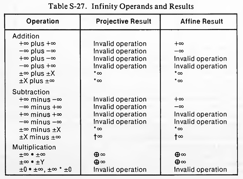
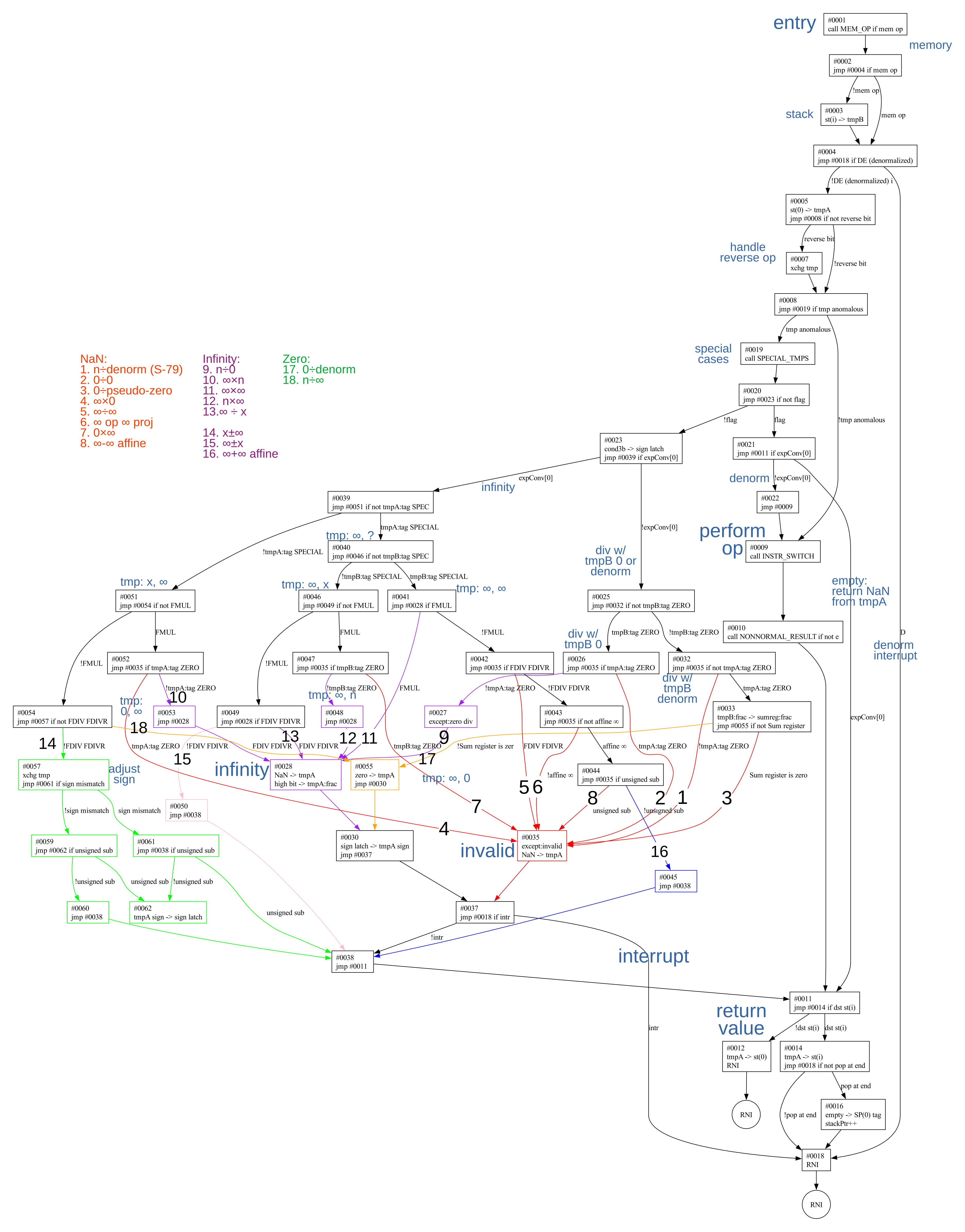
While these special cases make the 8087 more accurate mathematically, they make the microcode much more complicated. The microcode below is common to addition, subtraction, multiplication, and division. It loads arguments and stores the result as described above, but for the most part, it handles special cases. This microcode is "spaghetti code", with 18 conditional branches in a row to handle numerous special cases. I'll describe it at a high level here; the flowchart in the footnotes7 provides details.
#0001 call MEM_OP if mem op maybe get args from memory
#0002 jmp #0004 if mem op
#0003 st(i) -> tmpB        get from stack
#0004 jmp #0018 if DE (denormalized) interrupt quit if denormalized interrupt
#0005 st(0) -> tmpA        top of stack to tmpA
#0006 jmp #0008 if not reverse bit no jump if FSUBR, FMUL, FDIVR?
#0007 xchg tmp             reverse arguments
#0008 jmp #0019 if tmp anomalous handle anomalous values
#0009 call INSTR_SWITCH    switch on instruction type: J1(mul), J2(add/sub), J3(div)
#0010 call NONNORMAL_RESULT if not exp normal Back, finish up instruction
#0011 jmp #0014 if dst st(i) test d destination bit
#0012 tmpA -> st(0)        destination st(0)
#0013 RNI
#0014 tmpA -> st(i)        exit: destination st(i)
#0015 jmp #0018 if not pop at end RNI if not pop
#0016 empty -> SP(0) tag   mark top of stack empty
#0017 stackPtr++           pop
#0018 RNI
#0019 call SPECIAL_TMPS    handle special values
#0020 jmp #0023 if not flag
#0021 jmp #0011 if expConv[0] jump to finish
#0022 jmp #0009            switch on instruction type
#0023 cond3b -> sign latch more conditions
#0024 jmp #0039 if expConv[0]
#0025 jmp #0032 if not tmpB:tag ZERO
#0026 jmp #0035 if tmpA:tag ZERO
#0027 except:zero div
#0028 NaN -> tmpA          NaN, finish
#0029 high bit -> tmpA:frac
#0030 sign latch -> tmpA sign
#0031 jmp #0037            finish up
#0032 jmp #0035 if not tmpA:tag ZERO divide by denorm/0
#0033 tmpB:frac -> sumreg:frac divide by 0
#0034 jmp #0055 if not Sum register is zero
#0035 except:invalid
#0036 NaN -> tmpA
#0037 jmp #0018 if intr    jump to RNI
#0038 jmp #0011            finish
#0039 jmp #0051 if not tmpA:tag SPECIAL more conditions
#0040 jmp #0046 if not tmpB:tag SPECIAL
#0041 jmp #0028 if FMUL
#0042 jmp #0035 if FDIV FDIVR
#0043 jmp #0035 if not affine ∞ ∞×∞: test if affine
#0044 jmp #0035 if unsigned sub test if ∞ add or subtract
#0045 jmp #0038
#0046 jmp #0049 if not FMUL
#0047 jmp #0035 if tmpB:tag ZERO
#0048 jmp #0028
#0049 jmp #0028 if FDIV FDIVR
#0050 jmp #0038
#0051 jmp #0054 if not FMUL
#0052 jmp #0035 if tmpA:tag ZERO divide by 0?
#0053 jmp #0028
#0054 jmp #0057 if not FDIV FDIVR
#0055 zero -> tmpA         0÷denorm or n÷∞
#0056 jmp #0030            do something and finish up
#0057 xchg tmp
#0058 jmp #0061 if sign mismatch
#0059 jmp #0062 if unsigned sub test if adding or subtracting
#0060 jmp #0038            finish
#0061 jmp #0038 if unsigned sub finish
#0062 tmpA sign -> sign latch complement sign
#0063 !sign latch -> tmpA sign
#0064 jmp #0038            finish
Looking at #0008, the 8087 micro-architecture includes a conditional test that will check if either temporary
register is empty or is tagged with a special value.
If so, a subroutine that I call SPECAL_TMPS is called.8
It examines the two temporary registers and sets two flags to indicate what special
handling needs to be done.
If both flags are set, one of the arguments was tagged empty, typically indicating a stack underflow. In this case, the microcode returns Not-a-Number (NaN). If the second flag is clear, then one of the arguments was a denormal number, a special value very close to zero. The arithmetic operation continues in that case.
The remaining code paths get complicated, for example, branching on the signs of the arguments, the specific arithmetic operation, or if an argument is zero or infinity. Eight code paths return Not-a-Number: n÷denorm, 0÷0, 0÷pseudo-zero, ∞×0, ∞÷∞, 0×∞, ∞ op ∞ proj, and ∞-∞ affine. Many of these are straightforward—0×∞ has no meaningful value, for instance—but the last two need a bit more explanation.
The 8087 has two different modes for infinity, selected by a bit in the control register. With "affine closure", infinity is signed, so +∞ and -∞ are two different values. The recommended mode is "projective closure", where infinity is unsigned. In affine mode, ∞+∞ is perfectly valid, yielding positive infinity. However, ∞-∞ is meaningless; an answer of 0 would be arbitrary, so NaN is returned. In projective mode, none of the operations on infinity make sense because infinity is both infinitely positive and infinitely negative.
The microcode has eight different paths to return infinity: n÷0, ∞×n, ∞×∞, n×∞, ∞÷x, x±∞, ∞±x, and ∞+∞ affine. (The first case assumes that the divide-by-zero exception has been masked.) For the first five cases, the microcode generates the sign for infinity by combining the signs of the arguments. However, the last three cases take the sign from the infinity argument and ignore the other sign. In other words, multiplication and division can flip the sign of an infinity, but addition and subtraction can't.
Two paths deal with special-case 0 results: 0÷denorm and n÷∞. The microcode generates 0 with the correct sign, based on the signs of the arguments.
The leading zeros circuitry
With subtraction, digits can cancel out, leaving leading zeros that need to be removed by shifting the value. The 8087's shifter can shift a 64-bit value by an arbitrary number of bits. The job of the leading-zero circuitry is to count the leading zeros to determine how much to shift. That is, it counts how many zeros are to the left of the first 1 bit and turns this into a binary value. This is basically the same as a priority encoder that encodes the position of the first 1 bit.
Leading-zero circuits are somewhat complicated because each binary output bit depends on all the input bits; a 64-bit detector has 64 bits coming in. One approach is to take the truth table and optimize it, ending up with a pile of logic. Another approach is to use a hierarchical approach, a tree with log(N) stages. The 8087 takes a simpler path: one pass to eliminate leading zeros a byte at a time, and a second pass to eliminate the remaining 0 to 7 leading zero bits. Each pass requires a separate 8-input leading zero detector circuit. This approach is slower, but the circuitry is much simpler: two 8-bit leading zero detectors instead of a 64-bit leading zero detector.
The schematic below shows the circuit that converts 0 to 7 leading zeros into a 3-digit
binary value.
To simplify the schematic, I've replaced the first layer of logic with a bitmask that represents
the 8-bit input.
For instance, x01xxxxx indicates that the signal is high if the second bit is 0, the
third bit is 1, and the remaining bits are arbitrary.
I've added text descriptions; due to optimizations, the descriptions have some exceptions.
For instance, x01xxxxx matches anything with two leading zeros.
It also matches some patterns with no leading zeros, but those don't change the result.
The important thing is that it matches everything with 2 leading zeros and nothing with
1 or 3 leading zeros.
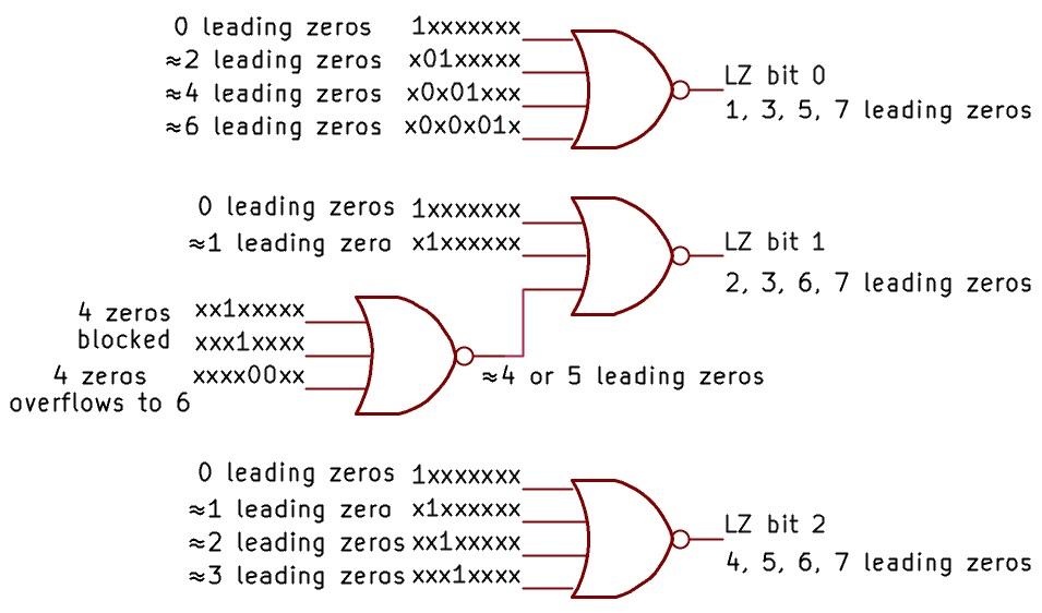
The output from the circuit is a 3-bit binary value representing the number of leading zeros. The top NOR gate generates the low bit, set for 1, 3, 5, or 7 leading zeros. The high bit is generated by the bottom NOR gate: set for 4, 5, 6, or 7. The middle bit is trickier, with an additional layer of logic to determine if there are 4 or 5 leading zeros (or maybe 0 or 1). The two 1 cases block four zeros, while the 00 pair means that four leading zeros would turn into at least 6. (This is a hand-waving explanation, but one can enumerate the 256 cases and verify that they all produce the correct answer.)
To count the number of bytes with leading zeros, similar logic is used. However, each group of 8 bits goes through an OR gate to detect if any bits are set in the byte. Thus, the logic determines how many bytes of leading zeros are present.
On the die, the leading zero logic is immediately to the left of the sum register, examining each bit of the sum register.
Conclusions
Most people don't give much thought to computer operations such as addition or subtraction. But there are interesting algorithms and special cases behind the scenes, and these features are embodied in clever silicon circuits. The intricate rules to handle positive and negative zeros, positive and negative infinities, and Not-a-Number are part of modern computers, since the 8087 led to the IEEE-754 floating-point standard used today. The 8087 went a bit overboard with special cases, however. Some 8087 features, such as projective infinity, unnormals, and pseudo-zero were dropped from the standard becauses they weren't worth the effort.
I plan to continue reverse-engineering the 8087 microcode; for updates, follow me on Bluesky (@righto.com), Mastodon (@[email protected]), or RSS. I've been working on this with the members of the "Opcode Collective", especially Smartest Blob and Gloriouscow, who converted the ROM images to microcode data and extensively analyzed the contents. See the 8087 repository on GitHub for more. AI statement: Despite the presence of the em dash, no AI was used in the writing of this article (details). The Opcode Collective used an ML algorithm to classify each ROM cell to extract the microcode.
Notes and references
-
Intel's documentation provides a performance comparison of the 8087 versus floating-point operations emulated on the 8086. The speedup varies depending on the instruction, but is typically almost a factor of 100. This speedup made the 8087 chip highly desirable for numerical applications such as CAD and spreadsheets. ↩
-
Internally, the 8087 uses 80 bits to hold floating-point values: one bit for the sign, 15 bits for the exponent, and 64 bits for the significand. However, the 8087 uses three extra low-order bits for rounding, called Guard, Round, and Sticky. These bits ensure that a value is always rounded in the right direction. Some parts of the datapath have additional bits for sign or overflow: the shifter is 68 bits wide, and the adder is 69 bits wide. For the most part, I'll ignore these extra bits and refer to the datapath as 64 bits wide. ↩
-
While floating-point numbers solve some problems, they introduce problems of their own. For instance, 0.01 can't be expressed exactly in floating point (it has an infinite repeating fraction in binary, just like 1/3 can't be expressed exactly as a decimal number). This can cause havoc if you're using floating-point numbers to represent money and you're dealing with cents. For more on problems with floating-point, see this Julia Evans comic or What Every Computer Scientist Should Know About Floating-Point Arithmetic. ↩
-
One difference between the 8087's temporary real format and the external formats is that in the temporary real, the leading 1 digit is explicitly stored in the number. In the external formats, the leading 1 is implicit and not stored in the number, providing one additional bit of accuracy, but making arithmetic more complicated. ↩
-
The flowchart below shows the control flow for the addition/subtraction microcode. (Click it for a larger image.)
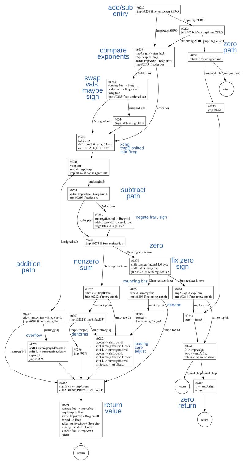 Flowchart of the add/sub microcode.
 -
William Kahan is the floating-point expert behind the 8087. He wrote about the motivations for various design decisions here, if you want the details of, for example, why NaN != NaN. (One interesting comment discusses the value of 00, commonly debated online. Kahan states, "A consensus is growing that x**0 = 1 for every x , including 0 , ∞ and NaN.") ↩
-
The flowchart below shows the microcode that is shared for basic arithmetic instructions. This flowchart calls the above flowchart as a subroutine. The numerous special case paths are numbered.
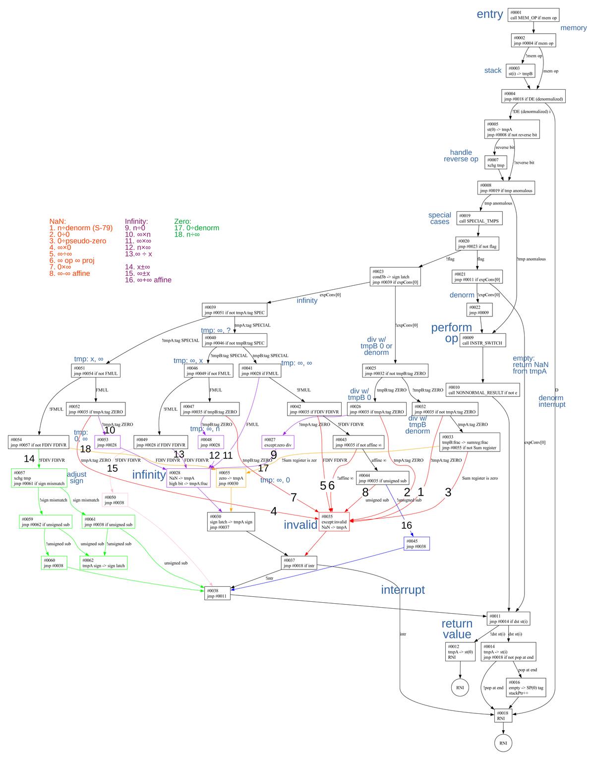 Flowchart of the common microcode for basic arithmetic operations. (Click for a larger image.)
 -
The actions of
SPECIAL_TMPSare summarized below. It returns status through theflagflip-flop and the exponent converter register (expConv). Its actions are:Input Result flag expConv empty NaN, exception 1 1 NaN (larger) NaN, exception 1 1 infinity infinity 0 1 denorm unnorm 1 0 divide-by-zero(ish) no change 0 0 The line I call "divide-by-zero(ish)" indicates that a division instruction is attempting to divide by zero or an unnormal number (which is close to zero). I'll give a bit of background on how the 8087 represents 0 and values near 0. A normal floating-point value has a mantissa with the first bit set. Unfortunately, normal numbers have a large gap between the smallest normal number and zero. Denormals break this "rule", allowing the top bits to be zero, so there are many more numbers near 0. (For a base-10 analogy, suppose you count down 1.003, 1.002, 1.001, 1.000. If the top digit must remain set, the next possible number is 0, a huge jump from 1.000. Denormals let you keep going in small steps: 0.999, 0.998, ...., 0.001, 0.)
For a denormal, the exponent has the smallest possible value. Unnormals are similar to denormals, except the exponent has a larger value. The purpose of unnormals is that if a denormalized exception is masked, the denormal number is converted to an unnormal and execution continues.
For true zero values, the 8087 uses a signed zero, so you can have either +0 or -0. A true zero is stored with the smallest possible exponent. But the 8087 also supports a "pseudo-zero", a zero value that has a larger exponent. The pseudo-zero can arise from multiplying two very small unnormal values. (With the 80387 floating-point chip, Intel got rid of unnormals and pseudo-zeros.)
I discussed the microcode for the
SPECIAL_TMPSsubroutine in detail earlier, so I won't discuss it more here. ↩